Step 04: Install Random Access Memory (RAM)
Consult the motherboard manual for the recommended Dual In-Line Memory Module (DIMM) slot configuration, open the slot retention latches, align the module key notch and press evenly until locked.
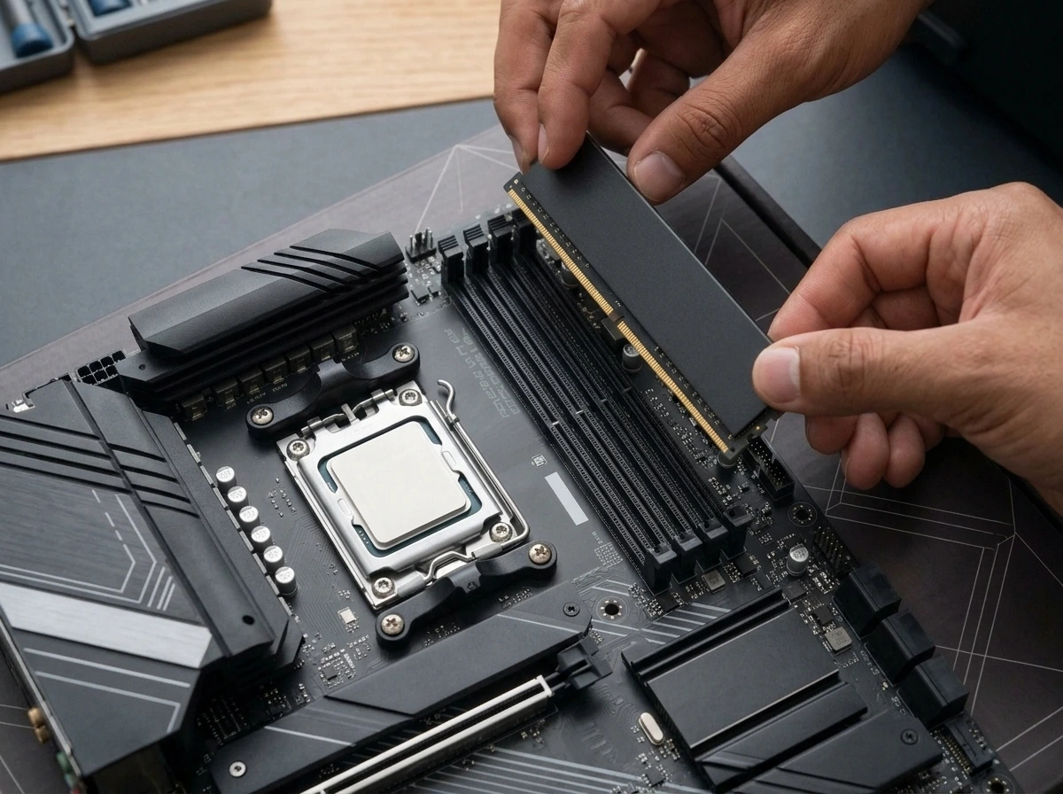
Step-by-Step Instructions
Identify the DIMM slots on the motherboard
Before handling memory modules, put on an anti-static wrist strap connected via an Electrostatic Discharge (ESD) grounding cord, then locate the two or four memory slots beside the Central Processing Unit (CPU) socket (typically labelled DIMM_A1, DIMM_A2, DIMM_B1 and DIMM_B2).
Consult the motherboard manual for the correct slots based on module count
Check your exact motherboard manual's memory population table for 1, 2 or 4 modules. While many four-slot boards recommend slots A2 and B2 first for two-module dual-channel operation, recommended slots vary by motherboard design and must always be confirmed in the board manual.
Open the required retention clips
Push the locking tabs outward at the ends of the target DIMM slots only. Note that some motherboards use dual-latch slots (clips open at both ends) while others use single-latch slots (one end opens and the opposite end is stationary; do not force a stationary clip).
Align the RAM notch with the slot key
Hold the memory module by its top corners or heat spreader edges and line up the off-centre notch along the bottom gold contacts with the raised key ridge inside the DIMM slot.
Press evenly until the module is fully seated and locks
Slide the module straight down into the slot guides, then press firmly and evenly with both thumbs on the top ends of the module until the retention clips snap upright into the side cutouts of the RAM stick.
Confirm that all installed modules are correctly secured
Inspect each populated slot from the side: the gold contact fingers at the bottom of the module should be evenly hidden inside the slot, all modules should stand at the exact same height and every retention latch must be fully closed.
Important Warnings & Precautions
- Never force a RAM module into a slot if the key notch does not line up; flip the module 180 degrees and verify that the RAM generation (DDR4 vs. DDR5) matches the motherboard.
- Do not press on a single-latch slot's fixed stationary end clip.
- An incompletely seated RAM module is one of the most common causes of a system failing to complete Power-On Self-Test (POST) on first boot.
Step 04 Completion Checklist
Confirm every item below before moving to the next step:
- Correct DIMM slots confirmed in the motherboard manual for your number of modules.
- Key notch aligned with the DIMM slot ridge before pressing down.
- Modules pressed down evenly until retention latches clicked into the side notches.
- All installed modules verified level and locked.
Relevant Components in This Step
Open any component page to review its physical parts, types and specifications: