Build Your Personal Computer (PC)
Follow this sequential sixteen-step guide to assemble, configure and test a complete desktop PC, from workspace preparation and Electrostatic Discharge (ESD) safety through Basic Input/Output System (BIOS) verification, operating-system installation, official driver setup and final stability testing.
Preparation and Safety
Verify hardware compatibility, prepare an Electrostatic Discharge (ESD)-safe workspace, inspect manuals and configure the case standoffs, Input/Output (I/O) shield and airflow plan.
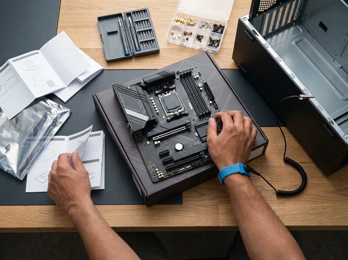
Safety, Compatibility and Workspace
Verify full hardware compatibility, confirm every cable and screw is present, review manufacturer manuals and set up a clean, static-controlled work surface.
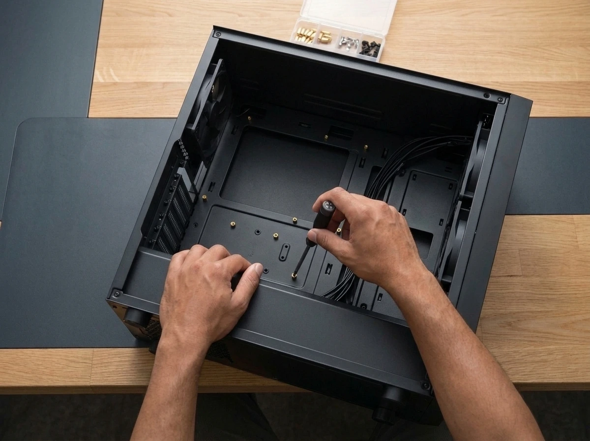
Prepare the Case and Cooling Layout
Remove case panels, verify motherboard standoff locations, install a separate rear Input/Output (I/O) shield if required, plan intake/exhaust airflow and pre-route front-panel cables.
Assemble the Core Components
Populate the motherboard outside the case on its cardboard box by installing the Central Processing Unit (CPU), Random Access Memory (RAM) modules, M.2 Solid-State Drives (SSDs) and cooling solution.
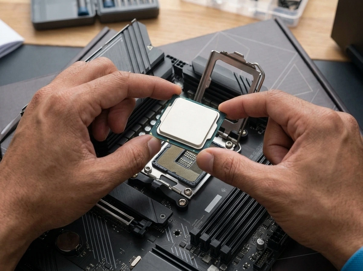
Install the Central Processing Unit (CPU)
Place the motherboard on its cardboard box, open the socket retention mechanism, align the Pin 1 marker and keying notches, and seat the processor gently without touching contacts.
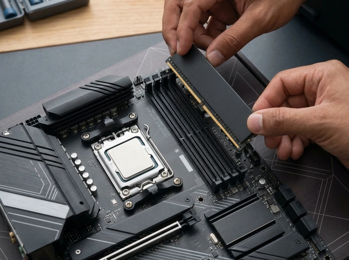
Install Random Access Memory (RAM)
Consult the motherboard manual for the recommended Dual In-Line Memory Module (DIMM) slot configuration, open the slot retention latches, align the module key notch and press evenly until locked.
Install M.2 Storage
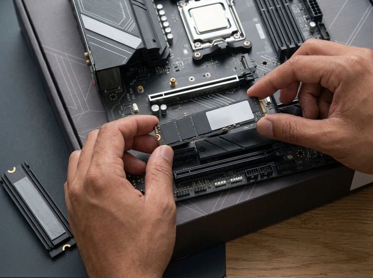
Select the primary M.2 slot, verify protocol and length support, insert the M.2 Solid-State Drive (SSD) at the specified angle, secure the standoff or latch, and remove thermal-pad film before reinstalling heatsinks.
Install the Central Processing Unit (CPU) Cooler
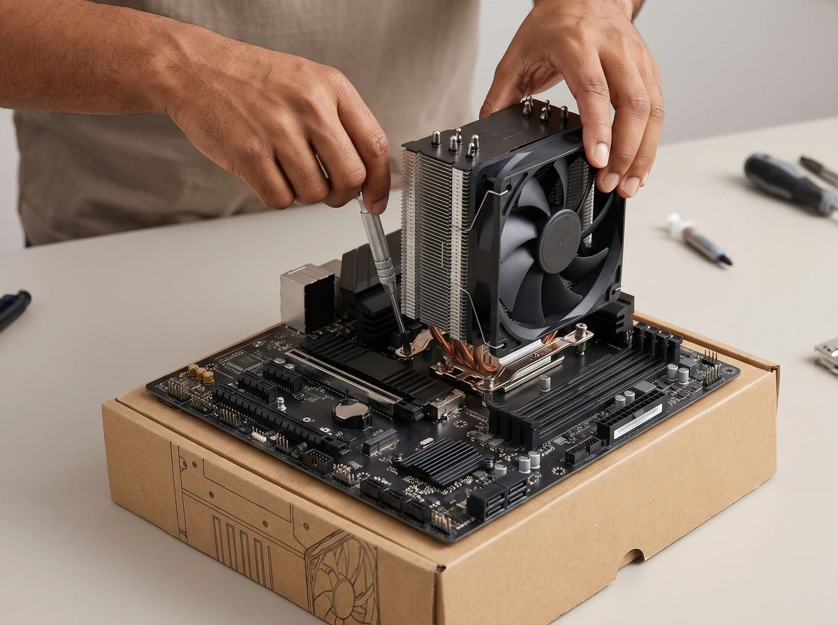
Follow the specific path for an Air Cooler or an All-in-One (AIO) Liquid Cooler: fit the socket brackets, remove cold-plate protective film, verify thermal compound, tighten evenly and connect fan/pump headers.
Assemble the System Unit
Mount the populated motherboard, power supply, storage drives and graphics card inside the chassis, connect all power, cooling and front-panel cables, and perform a full pre-power inspection.
Install the Motherboard
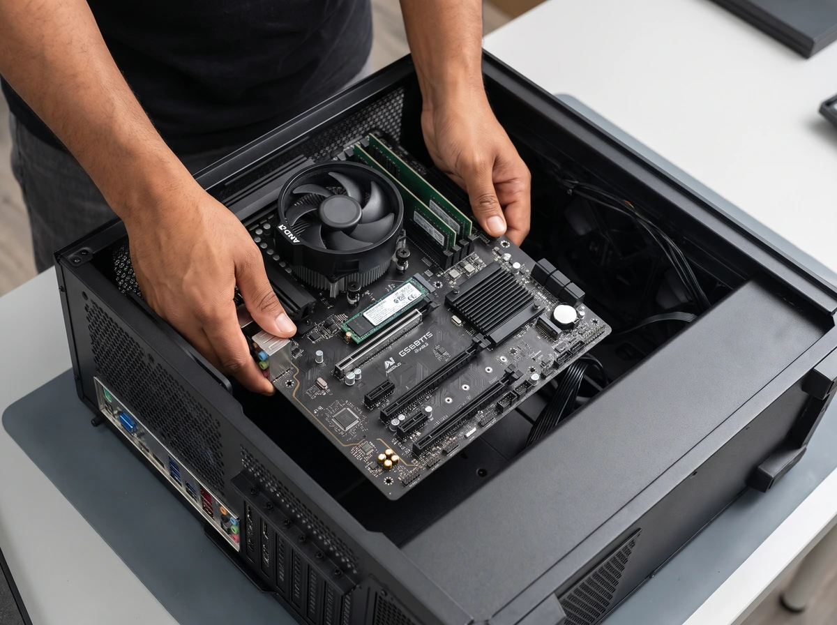
Verify standoffs and the rear Input/Output (I/O) shield, lower the populated motherboard into the chassis, align rear ports and mounting holes, and tighten the mounting screws evenly.
Install the Power Supply
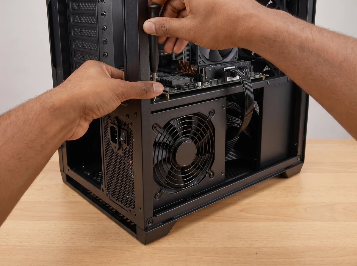
Orient the Power Supply Unit (PSU) intake fan toward a ventilated case opening, secure the unit with its four rear screws, attach compatible modular cables and route leads toward their destinations.
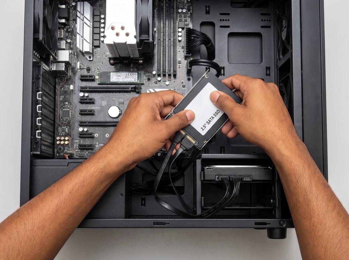
Install Serial Advanced Technology Attachment (SATA) Storage (Optional)
Optional for M.2-only builds: mount a 2.5-inch SATA Solid-State Drive (SSD) or 3.5-inch Hard Disk Drive (HDD) in its drive tray, connect the L-keyed SATA data cable to the motherboard and attach SATA power from the Power Supply Unit (PSU).
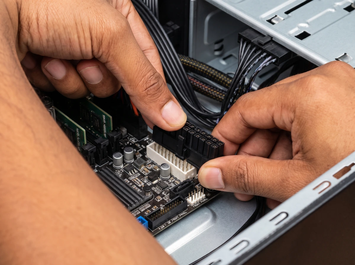
Connect Power, Fans and Case Cables
Connect the 24-pin Advanced Technology eXtended (ATX) and 4+4-pin Central Processing Unit (CPU) Entry-Level Power Supply (EPS) power cables, attach cooling fans and All-in-One (AIO) pump headers, wire the front-panel switches, light-emitting diode (LED) indicators, Universal Serial Bus (USB) and audio headers, and verify 5-volt (5 V) Addressable Red, Green, Blue (ARGB) vs. 12-volt (12 V) Red, Green, Blue (RGB) lighting.
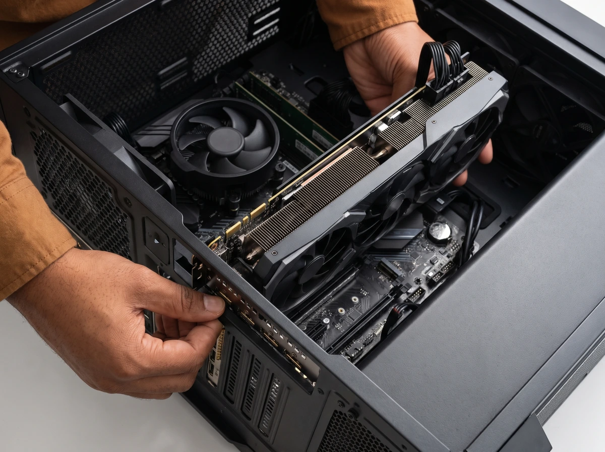
Install the Graphics Card (Optional for Integrated Graphics Processing Unit (iGPU) Builds)
Remove the matching rear Peripheral Component Interconnect Express (PCIe) slot covers, open the top PCIe x16 retention latch, seat the Graphics Processing Unit (GPU) evenly, screw the rear bracket to the case and connect PCIe 6+2-pin or 12-Volt (12 V) High Power (12VHPWR) / 12-Volt 2x6-pin (12V-2x6) power.
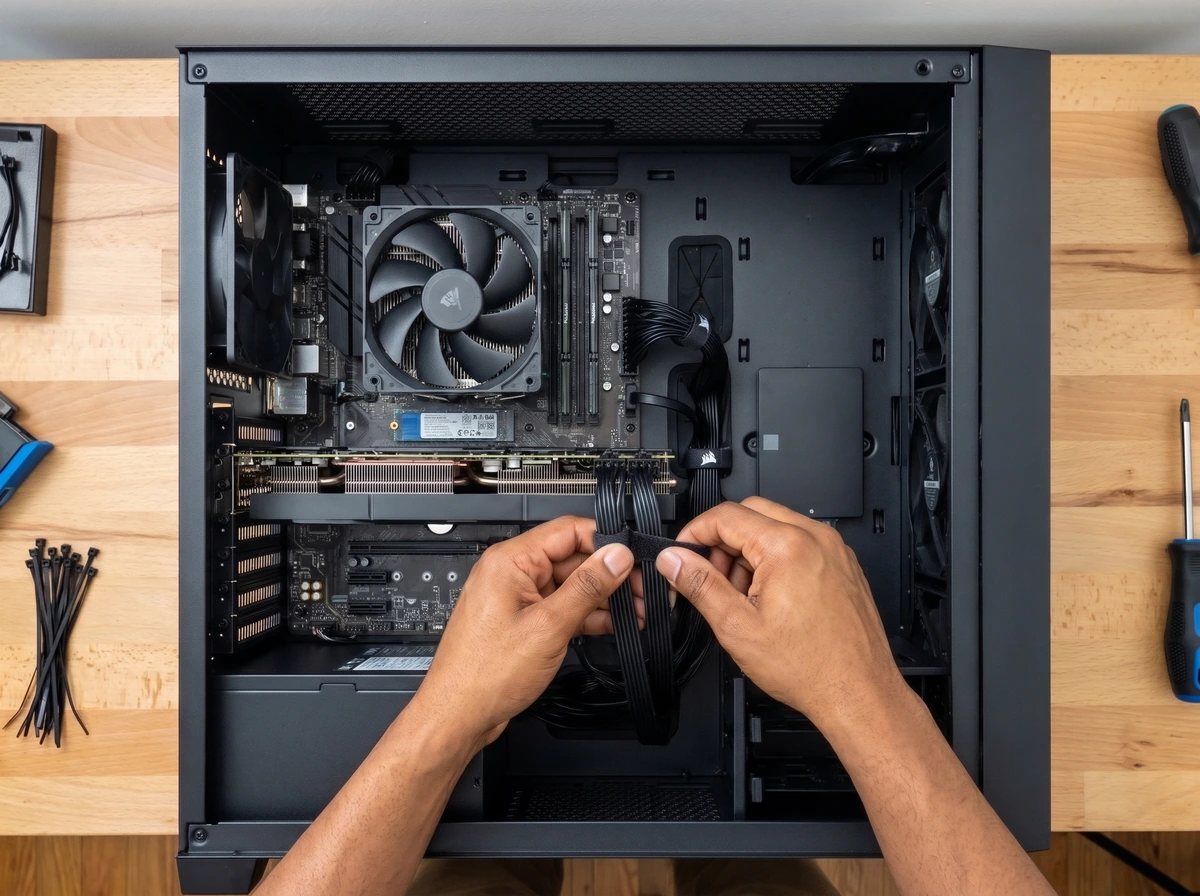
Final Cable Routing and Pre-Power Inspection
Route and bundle cables neatly away from fan blades, verify every component and power plug is seated, confirm cooler and M.2 films were removed, check for stray screws and leave the side panel open for first boot.
Start, Configure and Verify
Perform the first power-on and Basic Input/Output System (BIOS) / Unified Extensible Firmware Interface (UEFI) hardware check, install Windows 11 or Linux, install official hardware drivers, configure Extreme Memory Profile (XMP) / Extended Profiles for Overclocking (EXPO) memory profiles and run stability testing.
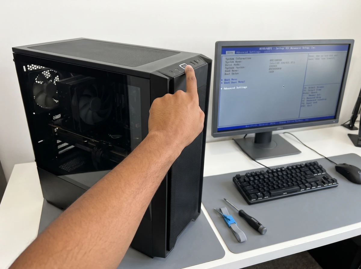
First Power-On and Basic Input/Output System (BIOS) / Unified Extensible Firmware Interface (UEFI)
Connect the monitor to the Graphics Processing Unit (GPU) (or motherboard for integrated Graphics Processing Unit (iGPU) builds), plug in alternating current (AC) power, turn on the Power Supply Unit (PSU), press the case power button, observe Power-On Self-Test (POST) and Double Data Rate 5 (DDR5) memory training, and verify hardware in BIOS/UEFI.
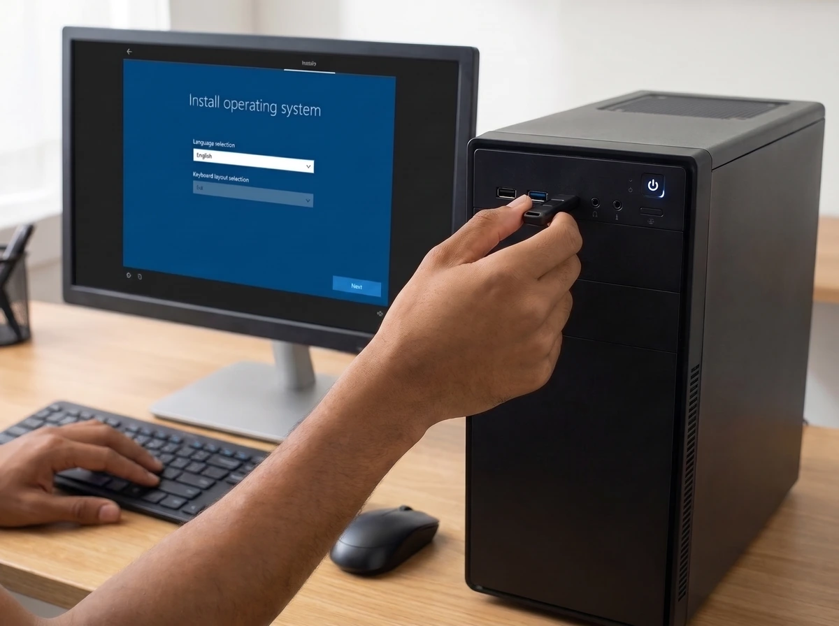
Install the Operating System
Prepare a bootable 16 to 32 gigabytes (GB)+ Universal Serial Bus (USB) flash drive from the official operating system (OS) source, boot into the installer via Unified Extensible Firmware Interface (UEFI), verify the target drive to protect existing data, and complete Windows 11 or Ubuntu/Linux installation.
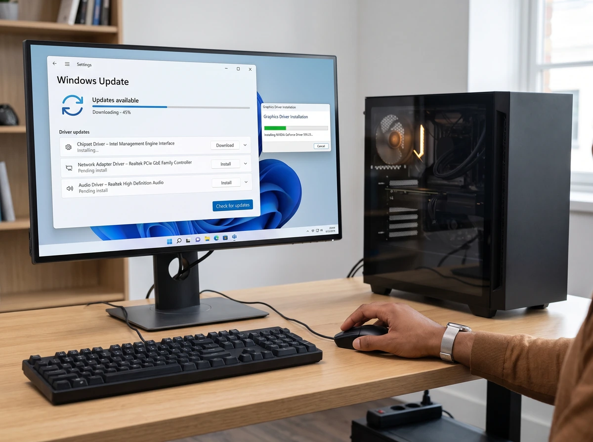
Install Drivers and Updates
Download and install official motherboard chipset, Ethernet, wireless networking (Wi-Fi), audio and NVIDIA, Advanced Micro Devices (AMD) or Intel graphics drivers, run operating system (OS) updates, check Device Manager for unknown devices and verify all storage drives.
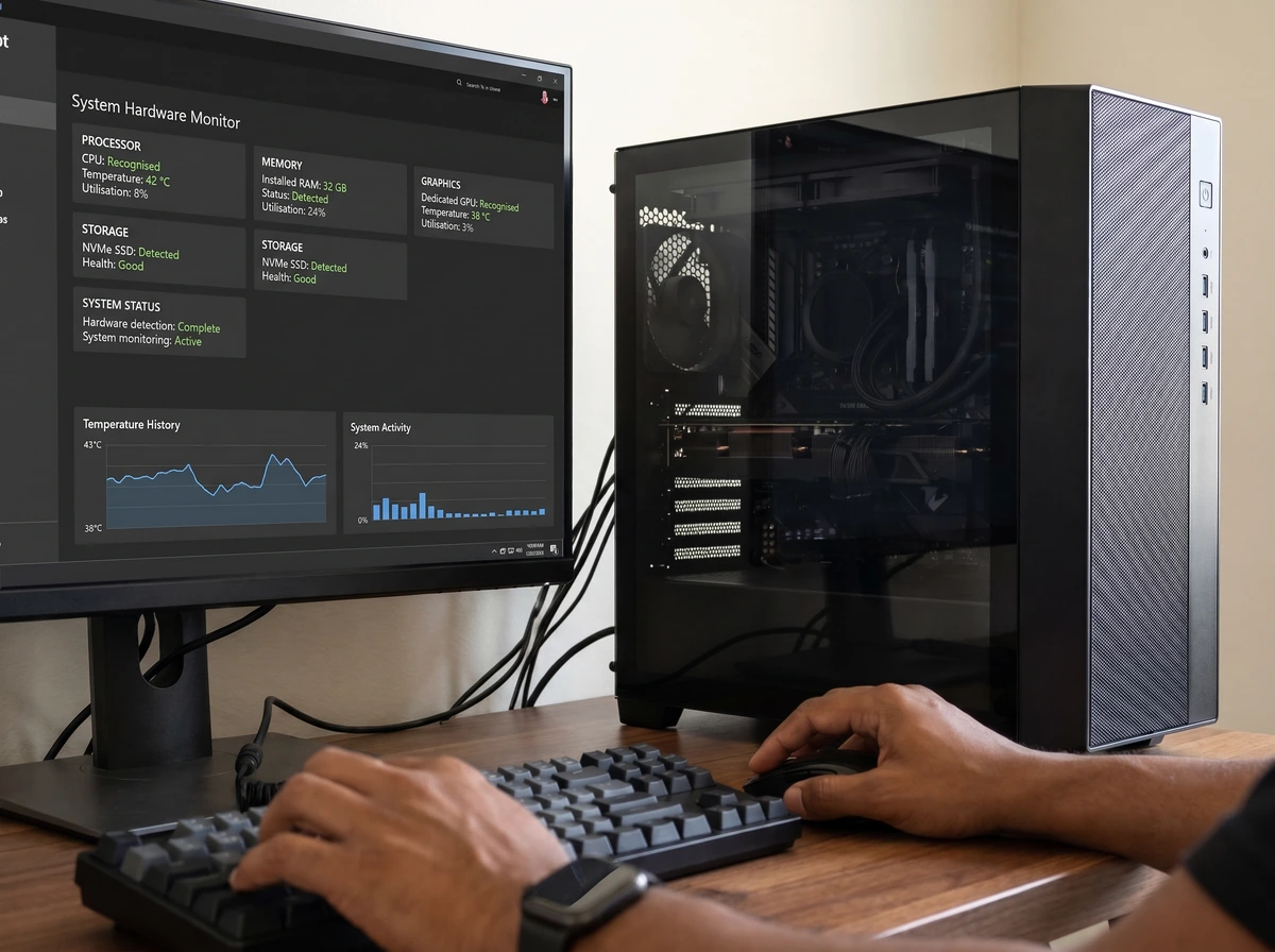
Final Configuration, Testing and Completion
Configure Extreme Memory Profile (XMP) and Extended Profiles for Overclocking (EXPO) memory profiles after verifying baseline stability, monitor cooling temperatures and fan curves, run Central Processing Unit (CPU), Graphics Processing Unit (GPU), Random Access Memory (RAM) and storage workloads, close the case panels and complete the build.