STAGE 02: ASSEMBLE THE CORE COMPONENTS · STEP 03 OF 16

Step 03: Install the Central Processing Unit (CPU)

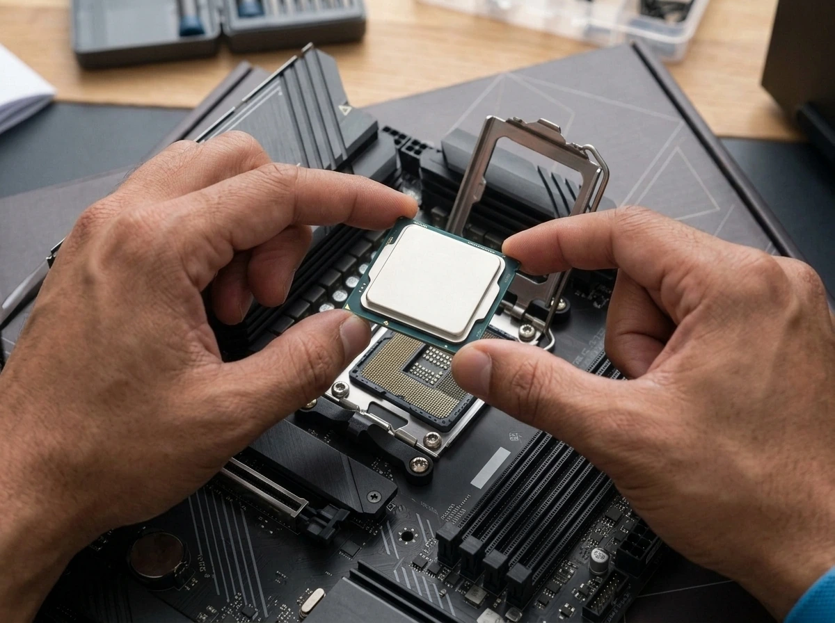
Place the motherboard on its cardboard box, open the socket retention mechanism, align the Pin 1 marker and keying notches, and seat the processor gently without touching contacts.

Caramel-brown fingers holding a desktop Central Processing Unit strictly by its printed circuit board edges and aligning it above an open silver Land Grid Array motherboard socket.
Close-up comparison of Intel Land Grid Array (LGA) and Advanced Micro Devices (AMD) AM5/AM4 CPU sockets showing Pin 1 triangle alignment markers, keying notches and retention lever operation.

Step-by-Step Instructions

  1. Place the motherboard on its box or appropriate Electrostatic Discharge (ESD)-safe work surface

    Lay the motherboard flat on top of its cardboard retail box. Do not place the board on its anti-static bag or on a metallic surface.

  2. Identify the CPU socket and its retention mechanism

    Locate the central processor socket on the motherboard and identify the retention lever and load plate (LGA) or zero-insertion-force locking arm (Pin Grid Array (PGA)).

  3. Open the socket according to the motherboard manufacturer's instructions

    Press the retention lever down slightly, move it outward away from the retention tab and lift it fully upright to raise the load plate (or unlock the socket). On LGA sockets with a plastic protective cover mounted inside the metal load frame, leave that plastic cover in place; it is designed to pop off automatically when you close the frame after seating the CPU.

  4. Remove the CPU from its packaging by holding its edges

    Grip the processor strictly by its substrate edges. Never touch the gold contact pads on the bottom of an LGA processor, the pins on a PGA processor or the delicate array of spring contacts inside an LGA motherboard socket.

  5. Identify and align the CPU's orientation marker and socket notches

    Locate the small gold triangle (Pin 1 indicator) on one corner of the CPU and match it to the corresponding Pin 1 triangle mark on the socket corner. Also verify that the alignment notches along the CPU edges match the alignment keys inside the socket frame.

  6. Lower the CPU gently and straight down into position

    Hold the CPU level and lower it straight down into the socket without tilting or sliding it across the contacts. It should rest flat and flush inside the socket under its own weight.

  7. Confirm that it is seated correctly before securing the retention mechanism

    Visually inspect all four corners to verify the CPU sits completely flat and keyed. Lower the retention frame, press the locking lever firmly down until it latches beneath its retention hook, and remove the popped-off plastic socket cover (keep this cover in the motherboard box in case the board ever needs warranty shipping).

A

Intel LGA Sockets (for example, LGA1700 / LGA1851) & AMD AM5 (LGA1718)

Land Grid Array (LGA) sockets place the delicate spring pins inside the motherboard socket while the bottom of the CPU has flat gold contact pads.

  • Release the retention lever and lift the metal load plate.
  • Leave the protective plastic cap attached to the load plate; do not pry it off over exposed socket pins.
  • Align the Pin 1 triangle and edge alignment notches, then lower the CPU straight down onto the socket contacts.
  • Lower the load plate over the CPU edges and push the retention lever down until locked; the plastic cap will eject automatically.
B

AMD AM4 PGA Sockets

Pin Grid Array (PGA) sockets place the metal pins on the underside of the CPU while the motherboard socket contains corresponding pin holes.

  • Lift the small metal retention arm at the side of the AM4 socket to a full 90-degree vertical position.
  • Match the gold triangle on the corner of the CPU with the triangle moulded into the corner of the socket.
  • Allow the CPU pins to drop effortlessly into the socket holes with zero downward force. If it does not drop flush on its own, stop and re-check alignment.
  • Hold a finger lightly on top of the CPU heat spreader and lower the retention arm back down until it latches at the side.

Important Warnings & Precautions

  • Never touch motherboard socket contacts or processor pins/pads with fingers or tools.
  • Never slide the CPU across the socket to find alignment; lift it straight up and realign.
  • Never force the processor into position or force the retention lever down if the CPU is tilted.
  • Never continue if the CPU does not align or seat completely flat in the socket.

Step 03 Completion Checklist

Confirm every item below before moving to the next step:

  • Motherboard supported flat on its cardboard box.
  • Pin 1 triangle and alignment notches matched between CPU and socket.
  • CPU seated completely flat with zero sliding or force.
  • Retention mechanism locked securely and protective socket cap stored safely in the motherboard box.

Relevant Components in This Step

Open any component page to review its physical parts, types and specifications:

Relevant Tools for This Step