Step 07: Install the Motherboard
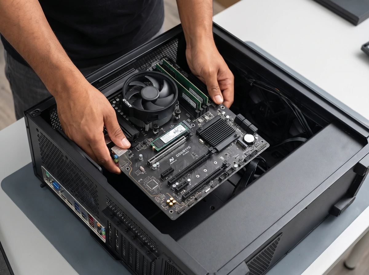
Verify standoffs and the rear Input/Output (I/O) shield, lower the populated motherboard into the chassis, align rear ports and mounting holes, and tighten the mounting screws evenly.
Step-by-Step Instructions
Confirm that the correct standoffs are installed
Double-check the case motherboard tray one final time to confirm a standoff is present for every hole on your motherboard and zero extra standoffs remain underneath.
Confirm that the separate I/O shield is installed, if required
If your motherboard does not have an integrated rear I/O shield, verify that the snap-in I/O shield is already locked into the rear case cutout in the correct orientation.
Lower the motherboard carefully into the case
Lay the case flat on its back side. Before handling the board, put on an anti-static wrist strap connected via an Electrostatic Discharge (ESD) grounding cord. Hold the motherboard by its edges or Voltage Regulator Module (VRM) heatsinks (never by the Random Access Memory (RAM) modules or frail headers) and lower it gently into the chassis, making sure no pre-routed case cables get trapped underneath the board.
Align the rear I/O ports and mounting holes
Slide the rear I/O connectors gently into the rear I/O cutout until the motherboard's screw holes sit directly centred over the brass standoffs. Check from the outside of the case that no metal grounding tabs from a separate I/O shield have slipped inside a Universal Serial Bus (USB) or Ethernet port.
Ensure every mounting hole aligns with a standoff
Look straight down through each metallised mounting hole around the perimeter and centre of the motherboard to verify the threaded brass standoff is visible underneath.
Install and tighten the supplied screws evenly
Verify in your case manual which metric or imperial screw thread fits your standoffs (typically metric M3 or #6-32). Thread all motherboard screws in loosely by a couple of turns first before tightening them in a diagonal pattern until snug. Do not overtighten.
Check that no loose standoff or metal object can contact the back of the motherboard
Inspect around and behind the motherboard tray to ensure no dropped screw or stray wire is wedged against the printed circuit board (PCB).
Important Warnings & Precautions
- Do not overtighten motherboard screws; stop as soon as the screw head seats snugly against the metallised ring around the mounting hole.
- Check the rear I/O panel from the outside of the case to make sure no metal grounding spring tab is poking inside a USB, High-Definition Multimedia Interface (HDMI) or Ethernet port.
- Never lift or manoeuvre the motherboard by pulling on installed RAM sticks or plastic headers.
Step 07 Completion Checklist
Confirm every item below before moving to the next step:
- All standoffs verified aligned with motherboard mounting holes.
- Rear I/O ports seated cleanly through the rear I/O shield with no obstructed ports.
- No cables or stray metal objects trapped beneath the motherboard.
- All motherboard mounting screws installed and tightened evenly without overtightening.
Relevant Components in This Step
Open any component page to review its physical parts, types and specifications: