STAGE 03: ASSEMBLE THE SYSTEM UNIT · STEP 08 OF 16

Step 08: Install the Power Supply

Orient the Power Supply Unit (PSU) intake fan toward a ventilated case opening, secure the unit with its four rear screws, attach compatible modular cables and route leads toward their destinations.

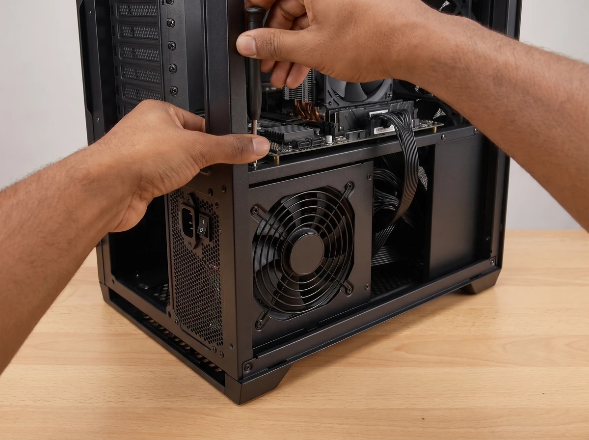
Caramel-brown hands installing a modern Advanced Technology eXtended power supply inside the lower chassis compartment and tightening its mounting screws with a screwdriver.
Seating the Advanced Technology eXtended (ATX) power supply inside the chassis PSU compartment with its alternating current (AC) switch off and tightening the case mounting screws.

Step-by-Step Instructions

  1. Identify the PSU mounting position

    Locate the power supply compartment (typically in the bottom rear shroud or rear chamber of the case). Keep the PSU power switch in the OFF (O) position and the AC wall cord unplugged.

  2. Orient the PSU fan toward an appropriate ventilated opening

    Check your case design and manual: if the bottom PSU bay has a filtered ventilation grille underneath, orient the PSU with its intake fan facing down so it draws cool outside air independently and exhausts out the back. If the mounting bay is solid metal with no bottom vent, follow the case manual's orientation guidance.

  3. Secure the PSU using its supplied screws

    Note: For cramped modular PSU bays, it is often easiest to plug your required modular cables into the PSU first before sliding the unit into the bay. Align the PSU's four rear mounting holes with the back of the case and fasten all four coarse-thread PSU screws.

  4. For modular PSUs, connect only cables confirmed compatible with that exact PSU

    Identify each labelled socket on the PSU housing (for example, motherboard 24-pin (MB), Central Processing Unit (CPU), Peripheral Component Interconnect Express (PCIe), 12-Volt (12 V) 2x6-pin (12V-2x6) / 12-Volt High Power (12VHPWR), and Peripheral / Serial Advanced Technology Attachment (SATA)) and push the PSU-side connectors in until their locking clips click.

  5. Route the cables toward their destinations

    Feed the 24-pin ATX cable toward the right edge of the motherboard, the CPU Entry-Level Power Supply (EPS) cable(s) up to the top-left corner behind the motherboard tray, the Graphics Processing Unit (GPU) power cable(s) toward the PCIe x16 area and any SATA power cable toward the drive bays.

CABLES

PSU Power Connectors: Purpose and Identification

Modern power cables are keyed and labelled on the connector housing so each rail reaches the correct component:

  • 24-Pin ATX Motherboard Power: Wide 24-pin (or 20+4-pin) main connector that supplies power to the motherboard chipset, PCIe slots, Random Access Memory (RAM) and onboard devices.
  • 4+4-Pin (8-Pin) CPU EPS Power: Labelled 'CPU' or 'EPS'; splits into two 4-pin halves (4+4) and plugs into the top-left ATX_12V / CPU_PWR header(s) to power the processor Voltage Regulator Modules (VRMs).
  • PCIe 6+2-Pin GPU Power: Labelled 'PCIe' or Video Graphics Array ('VGA'); splits into a 6-pin block plus a 2-pin side piece (6+2) and plugs into dedicated graphics cards.
  • 12VHPWR / 12V-2x6 GPU Power (where applicable): High-power 16-pin (12 power pins + 4 sense pins) connector used by modern PCIe 5.0 / ATX 3.x graphics cards.
  • SATA Power: Wide, flat L-keyed 15-pin connector used to power 2.5-inch SATA Solid-State Drives (SSDs), 3.5-inch Hard Disk Drives (HDDs), All-in-One (AIO) pump controllers and powered fan or Red, Green, Blue (RGB) lighting hubs.

Important Warnings & Precautions

  • CRITICAL: 8-pin CPU EPS (4+4) and 8-pin PCIe GPU (6+2) cables have completely different 12 V and ground pinouts and are NOT interchangeable. Always read the 'CPU' or 'PCIe' label stamped on the connector and never force a plug.
  • CRITICAL: Never reuse modular PSU cables from another power supply brand or model unless the manufacturer explicitly confirms pinout compatibility. PSU-side pinouts are not standardised and mixing cables can immediately destroy drives and boards.
  • Never open the PSU casing under any circumstances.

Step 08 Completion Checklist

Confirm every item below before moving to the next step:

  • PSU fan oriented toward the appropriate ventilated case opening.
  • Only original or manufacturer-verified modular cables attached and clicked into the PSU.
  • PSU secured to the rear of the chassis with all four mounting screws.
  • CPU EPS (4+4) and PCIe GPU (6+2 / 12V-2x6) cables identified by their printed labels and routed to the correct openings.

Relevant Components in This Step

Open any component page to review its physical parts, types and specifications:

Relevant Tools for This Step

Optional (Only If Needed):