STAGE 03: ASSEMBLE THE SYSTEM UNIT · STEP 10 OF 16

Step 10: Connect Power, Fans and Case Cables

Connect the 24-pin Advanced Technology eXtended (ATX) and 4+4-pin Central Processing Unit (CPU) Entry-Level Power Supply (EPS) power cables, attach cooling fans and All-in-One (AIO) pump headers, wire the front-panel switches, light-emitting diode (LED) indicators, Universal Serial Bus (USB) and audio headers, and verify 5-volt (5 V) Addressable Red, Green, Blue (ARGB) vs. 12-volt (12 V) Red, Green, Blue (RGB) lighting.

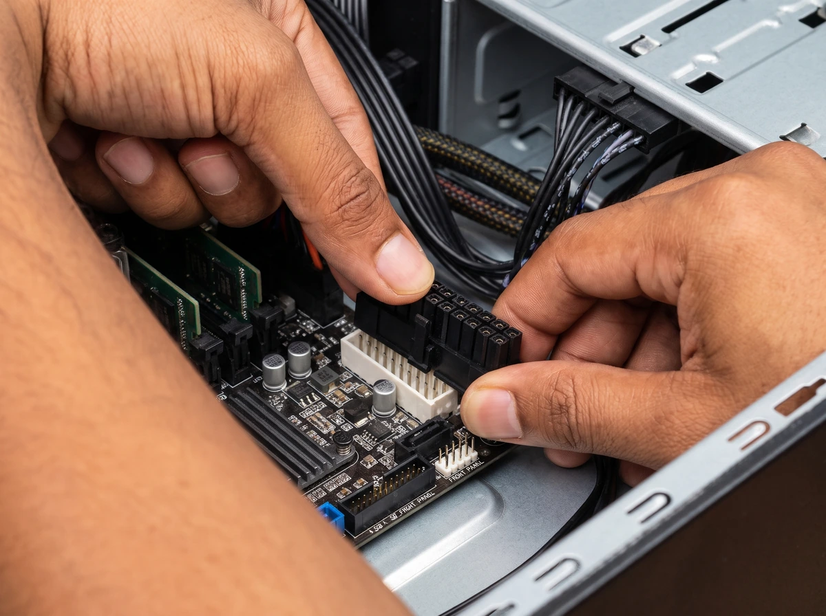
Caramel-brown hands aligning and pressing a 24-pin main power connector into the white motherboard power header beside storage and front-panel pins.
Aligning the keyed 24-pin ATX main power plug with the motherboard power socket beside Serial Advanced Technology Attachment (SATA) data ports and front-panel headers.

Step-by-Step Instructions

  1. Work systematically around the edges of the motherboard

    Before touching internal headers, wear your anti-static wrist strap connected to an Electrostatic Discharge (ESD) grounding point. Keep your motherboard manual open to the internal connectors page and complete the four groups of connections below one by one, verifying that every power latch clicks and every pin header is aligned before pressing down.

1

Motherboard and CPU Power Connections

Both the main motherboard power connector and the CPU power connector(s) must be connected for the computer to boot:

  • 24-Pin ATX Motherboard Connector (Destination: header labelled ATX_PWR1 / 24-pin socket on the right edge of the motherboard): Supplies main power to the motherboard. If the plug is split into 20+4 pins, hold both pieces flush together, align the retention latch with the catch on the socket and press firmly until the latch clicks completely shut with zero gap.
  • CPU EPS 4+4-Pin Connector (Destination: header labelled ATX_12V / CPU_PWR1 at the top-left of the motherboard): Supplies dedicated 12V power to the processor voltage regulators. Slide the two 4-pin halves together if using an 8-pin header, align the clip and press until latched. Connect the primary 8-pin CPU header first (connect the optional secondary 4-pin or 8-pin header as well if provided by your Power Supply Unit (PSU)).
2

Cooling Connections (CPU Cooler, AIO Pump and Case Fans)

Connect fans and pumps to their designated 4-pin Pulse Width Modulation (PWM) headers so the motherboard can monitor revolutions per minute (RPM) and regulate cooling:

  • CPU Cooler Fan → CPU_FAN Header: Plug the primary CPU air-cooler fan (or AIO radiator fan splitter) into the 4-pin CPU_FAN header near the top of the motherboard, aligning the plastic channel on the connector with the guide tab on the header.
  • Additional CPU Cooler Fans → CPU_OPT or Splitter: If a dual-tower air cooler has a second fan, connect it to CPU_OPT or via the cooler's supplied Y-splitter to CPU_FAN.
  • AIO Pump → AIO_PUMP / W_PUMP+ (or as prescribed by the AIO manual): Connect the pump unit's lead to the motherboard's dedicated pump header (or CPU_FAN if instructed by the cooler manual) and attach any required SATA power or internal USB 2.0 control cable.
  • Case Fans → SYS_FAN / CHA_FAN Headers or Powered Fan Hub: Connect individual chassis intake and exhaust fans to the motherboard's SYS_FAN / CHA_FAN 4-pin headers, aligning the 3-pin/4-pin guide tab.
3

Case Front-Panel Connections (Switches, LEDs, USB and Audio)

These cables link the buttons, indicator lights, USB ports and headphone jack on the outside of the case to the motherboard:

  • System Front-Panel Header (labelled F_PANEL / JFP1, usually bottom-right corner): Consult the exact pinout diagram in your motherboard manual. Some modern cases combine these into a single block connector; if your case uses individual 1-pin and 2-pin leads, connect them as follows:
  • Power Switch (labelled POWER SW, 2-pin) & Reset Switch (labelled RESET SW, 2-pin, if present): Momentary switches that turn on or restart the personal computer (PC). Polarity (+/-) does NOT matter for Power SW or Reset SW, though orienting the printed text outward keeps them tidy.
  • Power LED (labelled PLED+ / PLED-, 1-pin or 2-pin) & Storage Activity LED (labelled Hard Disk Drive (HDD) LED+ / -, 2-pin): Light-emitting diodes only work in one electrical direction, so polarity DOES matter. Match the positive (+) wire (marked with a small triangle on the back of the plastic plug or a coloured wire) to the + pin on the motherboard diagram, and the negative (-) wire to the - pin.
  • Front USB 2.0 (Destination: header labelled USB_12 / F_USB 9-pin header along the bottom edge): Features 9 pins with 1 missing corner pin (key). Align the blocked hole on the plug with the missing pin, and never plug USB 2.0 into an Institute of Electrical and Electronics Engineers (IEEE) 1394 or RGB header.
  • Front USB 3.x (Destination: USB 3.2 Gen 1 19-pin header, typically below the 24-pin ATX socket): Wide rectangular connector with a perimeter alignment notch. Line up the notch carefully and push straight in without rocking side-to-side so the fine pins inside do not bend.
  • Front USB Type-C (Destination: USB 3.2 Gen 2 / Gen 2x2 Key-A Type-E header, if equipped on both case and motherboard): Reversible metal-shrouded internal plug with subtle asymmetrical keying; test the orientation gently and press straight in until it clicks.
  • Front High Definition (HD) Audio (Destination: header labelled AAFP / JAUD1 9-pin header at the bottom-left corner): Powers the case's front headphone/microphone jack. The missing pin is second from the end; do not confuse it with USB 2.0 (whose missing pin is at the very corner).
4

Fan and RGB Controllers (5V ARGB vs. 12V RGB)

Powered hubs and lighting headers allow multiple fans and LED strips to operate from a single motherboard header:

  • How Powered Fan Hubs Work: A powered fan hub draws electrical power directly from the PSU via a 15-pin SATA power connector while connecting a single 4-pin PWM control cable to one motherboard SYS_FAN header, allowing several fans to follow one speed curve without overloading a single motherboard header.
  • 5V Addressable RGB (3-Pin ARGB / labelled JARGB_V2 / ADD_GEN2): Uses a 4-pin footprint with one gap [pin-pin-gap-pin] operating at 5 volts for individually addressable digital LEDs.
  • 12V Standard RGB (4-Pin RGB / labelled JRGB / RGB_HEADER): Uses 4 continuous pins [pin-pin-pin-pin] operating at 12 volts where all LEDs show the same colour simultaneously.
  • CRITICAL VOLTAGE WARNING: Never attempt to connect a 5V 3-pin ARGB device to a 12V 4-pin RGB header (or vice versa), because applying 12V to 5V LEDs will permanently burn out the LEDs.

Important Warnings & Precautions

  • Ensure the 24-pin ATX and 8-pin CPU EPS power connectors are pushed all the way in until their clips latch; a half-inserted CPU or 24-pin plug will prevent the system from powering on.
  • Take extreme care aligning the 19-pin Front USB 3.x plug straight before pressing; rocking or forcing it at an angle easily bends the thin pins inside the motherboard socket.
  • Never connect 5V 3-pin ARGB lighting to a 12V 4-pin RGB header, and always connect SATA power from the PSU to any powered fan or ARGB hub.

Step 10 Completion Checklist

Confirm every item below before moving to the next step:

  • 24-pin ATX motherboard power and 4+4-pin / 8-pin CPU EPS power fully seated and latched.
  • CPU cooler fan connected to CPU_FAN; AIO pump and case fans connected to their designated headers.
  • Front-panel Power SW, Reset SW, Power LED (+/- polarity verified) and HDD LED (+/- polarity verified) connected according to the motherboard pinout.
  • Front USB 2.0, USB 3.x, USB Type-C (if present) and HD Audio connected to their keyed headers.
  • Any fan/lighting hub connected to SATA power and matched strictly to the correct 5V ARGB or 12V RGB header.

Relevant Components in This Step

Open any component page to review its physical parts, types and specifications:

Relevant Tools for This Step