STAGE 03: ASSEMBLE THE SYSTEM UNIT · STEP 11 OF 16

Step 11: Install the Graphics Card (Optional for Integrated Graphics Processing Unit (iGPU) Builds)

Remove the matching rear Peripheral Component Interconnect Express (PCIe) slot covers, open the top PCIe x16 retention latch, seat the Graphics Processing Unit (GPU) evenly, screw the rear bracket to the case and connect PCIe 6+2-pin or 12-Volt (12 V) High Power (12VHPWR) / 12-Volt 2x6-pin (12V-2x6) power.

Note: Optional for Integrated-Graphics Builds: If your system relies solely on graphics integrated into the Central Processing Unit (CPU) (and does not include a dedicated graphics card), you may proceed directly to Step 12.
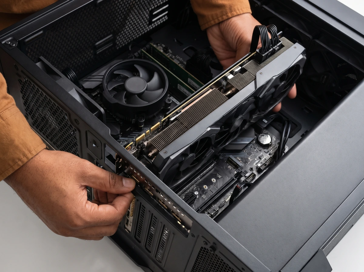
Caramel-brown hands aligning a triple-fan dedicated graphics card with the motherboard's primary expansion slot and rear case opening.
Lowering a dedicated graphics card into the primary PCIe x16 slot while aligning its metal expansion bracket against the rear case opening.

Step-by-Step Instructions

  1. Identify the motherboard's primary PCIe x16 slot

    Locate the full-length PCIe x16 slot closest to the CPU socket, as this slot connects directly to the processor's full x16 PCIe lanes for maximum graphics bandwidth.

  2. Remove the appropriate rear expansion-slot covers

    Hold the graphics card briefly above the slot to see which two or three rear case expansion-slot covers align with its metal Input/Output (I/O) bracket, then unscrew and remove those slot covers from the back of the case.

  3. Open the PCIe retention latch where applicable

    Press down the plastic or metal retention tab (or press the motherboard's quick-release PCIe button) at the right end of the primary PCIe x16 slot so it is in the open position.

  4. Align the GPU with the slot and insert it evenly until fully seated

    Remove any protective plastic strip covering the GPU's gold PCIe edge connector. Guide the rear metal bracket tangs cleanly into the gap between the motherboard and the rear of the case, align the gold edge connector with the PCIe x16 slot and press straight down evenly until the retention latch clicks shut.

  5. Secure its rear bracket to the case

    Always support heavy graphics cards while fastening the rear bracket screws into every mounting hole on the card's I/O bracket so the PCIe slot does not bear unsupported weight.

  6. Install a suitable GPU support bracket where needed

    For long or heavy two-and-a-half to four-slot graphics cards, install the included anti-sag support pillar or case bracket underneath the far corner of the card shroud (making sure the support does not touch the GPU fan blades).

  7. Connect the correct GPU power cable

    Connect the required PCIe 6+2-pin / 8-pin or 12VHPWR / 12V-2x6 power cable(s) from the Power Supply Unit (PSU) according to the specific requirements below.

  8. Verify that all power connectors are fully inserted and latched

    Inspect every GPU power plug closely from the side and top to confirm the connector face sits completely flush against the socket and the retention clip is locked.

A

Conventional PCIe 6+2-Pin / 8-Pin GPU Power Connections

Used on cards with one, two or three 8-pin (or 6-pin) PCIe power sockets:

  • Use only cables marked 'PCIe' or Video Graphics Array ('VGA') (never a 4+4-pin CPU cable).
  • For an 8-pin socket, slide the 2-pin side piece together with the 6-pin block before inserting so all 8 pins seat to the exact same depth.
  • Whenever possible on high-wattage GPUs with two or three 8-pin ports, run separate dedicated PCIe power cables from the PSU rather than relying on a single cable's pigtail daisy-chain.
  • Confirm every 8-pin socket on the card is populated and latched.
B

12VHPWR / 12V-2x6 (16-Pin) GPU Power Connections

Used on modern high-power graphics cards with a compact 12+4-pin connector:

  • Confirm full, straight insertion: Push the 16-pin connector straight into the GPU socket until the latch clicks into place.
  • Ensure there is zero visible gap: Inspect the seam between the plug and the GPU socket from all sides; there must be no visible gap anywhere along the housing.
  • Follow the cable manufacturer's bend-clearance guidance: Allow a straight run (typically at least 30 to 35 millimetres (mm)) out of the connector before making any gradual bend, and avoid sharp sideways or vertical strain on the plug when closing the side panel.
  • Do not use unsuitable or unverified third-party adapters: Use either the native 12V-2x6 / 12VHPWR cable supplied with your Advanced Technology eXtended (ATX) 3.x PSU or the official multi-8-pin adapter included with the graphics card (with every input leg connected to a separate PSU cable).

Important Warnings & Precautions

  • A partially inserted 12VHPWR / 12V-2x6 connector with a visible gap or sharp bend right at the plug can overheat under load, so always verify a 100% flush, gap-free connection.
  • Always unlock the PCIe x16 slot's retention tab before ever pulling a graphics card out of the motherboard.

Step 11 Completion Checklist

Confirm every item below before moving to the next step:

  • Primary PCIe x16 slot used and matching rear slot covers removed.
  • GPU gold edge connector fully seated with PCIe retention latch locked.
  • Rear I/O bracket screwed securely to the case (and anti-sag support fitted if needed).
  • All GPU power connectors (PCIe 6+2-pin or 12V-2x6/12VHPWR) fully inserted with zero gap and latched.

Relevant Components in This Step

Open any component page to review its physical parts, types and specifications: