Step 12: Final Cable Routing and Pre-Power Inspection
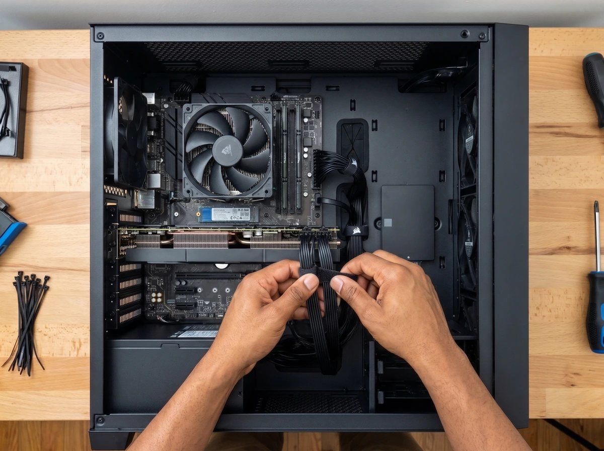
Route and bundle cables neatly away from fan blades, verify every component and power plug is seated, confirm cooler and M.2 films were removed, check for stray screws and leave the side panel open for first boot.
Step-by-Step Instructions
Route excess cables behind the motherboard tray where possible
Draw slack out of the main chamber through the rubber grommets or routing cutouts into the rear cable-management channel and lower Power Supply Unit (PSU) shroud so internal airflow from front to back is completely unobstructed.
Bundle cables using existing Velcro ties or suitable zip ties
Use the case's built-in Velcro straps or reusable Velcro cable ties for preliminary bundling so cables remain easy to adjust until after you verify first boot. If using nylon zip ties, pull them snug without crushing wire insulation and trim tails flush with flush cutters.
Keep cables away from fan blades
Spin every case fan, Central Processing Unit (CPU) cooler fan and Graphics Processing Unit (GPU) fan gently by hand to verify that no fan wire, Red, Green, Blue (RGB) lighting lead or power cable can droop into the blades.
Make sure no cable is pinched by a panel or sharp edge
Check that thick 24-pin and GPU cables lie flat inside the rear routing channels and do not cross over raised frame lip edges where closing a panel could pinch the insulation.
Check that Random Access Memory (RAM), GPU and storage are seated correctly
Visually verify that every RAM stick's side clips are locked, the GPU sits level and latched in the Peripheral Component Interconnect Express (PCIe) x16 slot, and M.2 / Serial Advanced Technology Attachment (SATA) drives are secure.
Confirm that all required motherboard, CPU, GPU, storage and fan connections are secure
Press-check the 24-pin Advanced Technology eXtended (ATX) plug, 8-pin CPU Entry-Level Power Supply (EPS) plug(s), GPU power connector(s), SATA power/data cables, primary CPU fan (CPU_FAN) / All-in-One (AIO) pump (AIO_PUMP) leads and front-panel Power Switch (POWER SW) header.
Confirm that CPU cooler and M.2 heatsink protective films have been removed
Mentally and visually confirm that the plastic protective stickers were peeled off the CPU cooler cold plate and any M.2 heatsink thermal pads.
Check fan orientation and physical clearance
Confirm intake and exhaust fan orientations match your planned airflow and that GPU power cables have adequate bend clearance.
Check that no extra standoffs, loose screws, tools or metal objects remain inside the case
Inspect the motherboard surface, GPU backplate, PSU shroud and bottom of the case for any dropped screw, bit or loose standoff.
Leave the side panel open for the first power-on inspection
Keep the main side panel off for Step 13 so you can directly observe fans spinning up, diagnostic light-emitting diodes (LEDs) and pump operation on first power-on.
Important Warnings & Precautions
- Final Safety Check: The PSU must remain switched OFF and its alternating current (AC) power cord disconnected until all 10 pre-power inspection checks above are complete.
- Never use scissors or a knife near bundled wires if trimming nylon zip ties; use flush cutters angled away from the wire insulation.
Step 12 Completion Checklist
Confirm every item below before moving to the next step:
- Excess cable slack routed behind the motherboard tray away from airflow paths.
- All fan blades spun by hand and confirmed 100% clear of wires.
- RAM, GPU, M.2 and SATA drives confirmed fully seated and secured.
- 24-pin ATX, CPU EPS, GPU power, CPU_FAN and Front-Panel connectors verified latched.
- Zero loose screws, extra standoffs or tools inside the case; side panel left open for Step 13.
Relevant Components in This Step
Open any component page to review its physical parts, types and specifications: