STAGE 04: START, CONFIGURE AND VERIFY · STEP 13 OF 16

Step 13: First Power-On and Basic Input/Output System (BIOS) / Unified Extensible Firmware Interface (UEFI)

Connect the monitor to the Graphics Processing Unit (GPU) (or motherboard for integrated Graphics Processing Unit (iGPU) builds), plug in alternating current (AC) power, turn on the Power Supply Unit (PSU), press the case power button, observe Power-On Self-Test (POST) and Double Data Rate 5 (DDR5) memory training, and verify hardware in BIOS/UEFI.

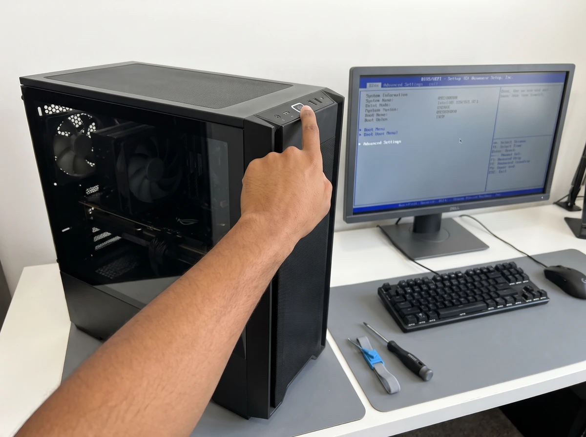
Caramel-brown hand pressing the desktop computer power button on the completed case as the connected monitor displays the system firmware setup screen.
Pressing the case power button for initial startup while the connected desktop monitor loads the system BIOS/UEFI Setup screen.

Step-by-Step Instructions

  1. Connect the monitor, keyboard and mouse

    Place the upright personal computer (PC) on your desk, plug the keyboard and mouse into the rear motherboard Universal Serial Bus (USB) ports and power on your monitor.

  2. Connect the display cable to the dedicated GPU (if installed)

    If your build includes a dedicated graphics card, plug your DisplayPort or High-Definition Multimedia Interface (HDMI) cable directly into one of the horizontal ports on the graphics card itself, NOT into the vertical video ports on the motherboard rear Input/Output (I/O) panel. Use the motherboard's video outputs only when building a system without a dedicated GPU (and only after confirming your Central Processing Unit (CPU) model includes integrated graphics).

  3. Connect the PSU AC cable

    Plug the power supply's thick 3-prong AC mains cord firmly into the back of the PSU and into a grounded wall outlet or surge protector.

  4. Switch on the PSU

    Flip the rocker switch on the back of the power supply from O (Off) to I (On). Note that flipping the PSU switch supplies standby power to the motherboard, but does not start the computer yet.

  5. Press the case power button

    Press the front-panel power button on the top or front of the PC case once.

  6. Observe the system's POST process, diagnostic light-emitting diode (LED) indicators and any error codes

    Watch through the open side of the case: case fans and CPU cooler fans should begin spinning, and the motherboard's diagnostic POST LEDs (typically four small LEDs labelled CPU, Dynamic Random Access Memory (DRAM), Video Graphics Array (VGA) and BOOT) will cycle one by one as each subsystem is tested.

  7. Allow the motherboard time to initialise, including DDR5 memory training

    Be patient on the very first boot! Modern platforms (especially DDR5 systems on Advanced Micro Devices (AMD) AM5 and Intel) perform initial memory training that can keep the screen blank with the DRAM LED lit for 1 to 3 minutes (and occasionally restart once or twice) before displaying an image. Do not force-power off the PC during initial memory training.

  8. Enter BIOS/UEFI using the motherboard's designated key

    As soon as the motherboard splash screen appears, tap the Delete or F2 key repeatedly (or press F1 if prompted by a 'New CPU Installed' message) to enter the BIOS/UEFI interface.

UEFI

Inside BIOS/UEFI: Essential Hardware Checks

On the main UEFI summary screen (EZ Mode / Dashboard), verify the following readings before installing an operating system:

  • CPU Detected: Confirm your exact processor model name and core count are displayed.
  • Random Access Memory (RAM) Capacity Detected: Confirm the total installed memory capacity (for example, 16 gigabytes (GB), 32 GB or 64 GB) matches all installed modules and shows dual-channel operation (note: RAM will run at its safe default Joint Electron Device Engineering Council (JEDEC) speed such as 4800 megatransfers per second (MT/s) or 2133/2666 MT/s until Step 16).
  • Storage Devices Detected: Confirm your M.2 Non-Volatile Memory Express (NVMe) Solid-State Drive(s) (SSDs) and any Serial Advanced Technology Attachment (SATA) SSDs or Hard Disk Drives (HDDs) appear under the storage list.
  • CPU Temperature: Confirm the CPU idle temperature in BIOS is stable in a normal range (typically around 30 degrees Celsius (°C) to 48 °C) and is not rapidly climbing toward 80 to 90 °C+ (which would indicate a loose cooler mount, unpeeled plastic film or disconnected All-in-One (AIO) pump).
  • CPU Fan and Pump Readings: Confirm revolutions per minute (RPM) values are reported for CPU_FAN, AIO_PUMP and connected case fans.
  • BIOS Version: Record the installed BIOS version and build date.
  • Basic Boot Configuration: Confirm UEFI boot mode (not legacy Compatibility Support Module (CSM)) is active.
  • Guidance on BIOS Updating: Updating the BIOS is NOT compulsory on every build. Update only when CPU/RAM compatibility, an important security/stability fix (such as voltage regulation updates) or a manufacturer recommendation requires it. Always follow the exact motherboard manual procedure (such as M-Flash, EZ Flash or BIOS FlashBack) and NEVER power off or interrupt a BIOS update.
POST

First-Boot Troubleshooting Quick Guide

Always switch OFF the PSU and unplug the AC cable before touching or reseating any internal component:

  • No Power at All (no fans spin, no LEDs): Confirm the PSU rocker switch is set to 'I', the wall outlet has power, the 24-pin Advanced Technology eXtended (ATX) and 8-pin CPU Entry-Level Power Supply (EPS) cables are fully latched, and the case Power Switch (labelled POWER SW) 2-pin lead is on the exact two power-switch pins of the front-panel header (labelled F_PANEL).
  • Fans Spin, but No Display on Monitor: Verify the monitor is switched to the correct input (DisplayPort vs. HDMI), confirm the display cable is plugged into the dedicated GPU (not the motherboard), wait at least 2 to 3 minutes for DDR5 memory training, and check which motherboard diagnostic light (labelled EZ-Debug LED) stays lit.
  • DRAM LED Stays Lit: Power off and unplug AC power, then firmly reseat the RAM modules until both ends click flush (or test with a single module in the primary slot specified by the motherboard manual, usually A2).
  • VGA LED Stays Lit: Power off and unplug AC power, reseat the graphics card in the Peripheral Component Interconnect Express (PCIe) x16 slot, and verify every GPU power connector (6+2-pin or 12-Volt (12 V) 2x6-pin (12V-2x6)) is fully inserted at both the GPU and PSU ends.
  • Missing Storage Drive in BIOS: Power off and unplug AC power, reseat the M.2 drive (and check whether the slot supports its NVMe/SATA protocol), or verify that both the SATA data and SATA power cables are connected for 2.5-inch/3.5-inch drives.

Important Warnings & Precautions

  • Always power down the system, switch off the PSU (O) and unplug the AC cord before reseating RAM, GPUs, drives or cables.
  • Do not interrupt the first boot during initial DDR5 memory training, and never interrupt an active BIOS update.

Step 13 Completion Checklist

Confirm every item below before moving to the next step:

  • Display cable connected to the dedicated GPU (or motherboard if using integrated graphics).
  • System powered on cleanly and entered BIOS/UEFI.
  • CPU model, full RAM capacity and all installed storage drives recognised in UEFI.
  • CPU temperature and fan/pump RPM readings confirmed normal and stable.

Relevant Components in This Step

Open any component page to review its physical parts, types and specifications:

Relevant Tools for This Step